Table Of Content
Whether implementing a new company-wide system or refining a department's existing process, a DFD gets you and your team on the same page. A DFD not only helps businesses maintain a clear view of how they interact with customers but also to identify ways to improve relationships. A DFD can be as simple or as complex as the system it represents, but the easiest way to make one is with a Data Flow Diagram tool. Why understanding the difference between customers and community is important when creating microsites. Your website is a user’s first glance into your business — here’s how you can cater intuitive design experiences for them. Mega menus enhance the user experience with organized, intuitive navigation.
Categorize related business activities.
Even if you’re just a beginner, our drag-and-drop functionality and simple interface will help you get started in no time. Start your data flow diagram with one of our templates or begin with a blank canvas. As mentioned above, not every DFD will need data stores, but if yours does, make sure to follow the same labeling method as for external entities, and differentiate them with a different symbol.
DFD hierarchy
(This is a common gotcha that will come up again later.) Then describe the app you want to build. Gary Hoberman is the founder and CEO of Unqork, an enterprise-grade codeless platform. Generally, DFDs are level 0, level 1, or level 2, though they can go higher in rare cases.
Rules for creating DFD
Now we will learn to transform the data flow diagram into a structure chart. A structure chart represents all the software components and how these components call each other when the software performs i.e. the relation between them. A data flow diagram aims to create a design with the best possible modularity. Modularity means that the individual components can be designed, tested, understood and changed without affecting the other component of the software. The independent component is the component that communicates with the other component only by inputting and outputting serial streams of data. The data flow diagram represents the data flow and data transformation within the software.
TransCelerate BioPharma Commences Collaborative Development of a Novel Digital Data Flow Solution for Study ... - Business Wire
TransCelerate BioPharma Commences Collaborative Development of a Novel Digital Data Flow Solution for Study ....
Posted: Thu, 09 Sep 2021 07:00:00 GMT [source]
You can either use logical or physical diagrams to describe that flow of information. You can also use them in conjunction to understand a process or system on a more granular level. Unsurprisingly, data analysts are some of the most common professionals to benefit from a DFD. Data analysts are responsible for mining data and finding insights, so the structure and system requirements of data flows are critical to their work.
Data Flow Diagram
DFD was highlighted in the book “Structured Design” by Ed Yourdon and Larry Constantine in the 1970s. With the success of the structures design concept in the software engineering field, people began to acknowledge DFD as a useful tool. From there, its scope of usage expanded, especially in business circles. By visualizing the system flow, the flow charts will give users helpful insights into the process and open up ways to define and improve their business. While data flow architectures can be designed to scale, managing the scaling process itself can be complex.
Unique Name for Levels
They look at how many people are watching, their location, and how long they watch a particular video. This data helps video producers to make their programs better and focus on engaging content that aligns with viewers' preferences and holds their attention for longer durations. Moreover, the data collected by BlaBlaCar allows them to dynamically adjust pricing based on real-time demand and supply. A ride-sharing service, BlaBlaCar captures data and constantly collects information about its users' locations, travel times, and budgets.
Overview: What is a data flow diagram?
They can be used alongside the user-defined local or global variables mentioned above. These special variables are defined at the organization level and used across multiple flows, particularly for reporting purposes. When set within a flow, global variables can be reported in Analyzer. Local variables can be collected by global variables for use in reporting. Components of the software are a set of code lines that include data and the functions to perform on the data.
Map your system or process
Copilot then saves the Dataverse table and creates a new canvas app with a simple UI to display your data. Depending on which environment you started in, you might get an error message about not having proper access. I was accidentally in my default environment when I began creating the app, which is easy to do.
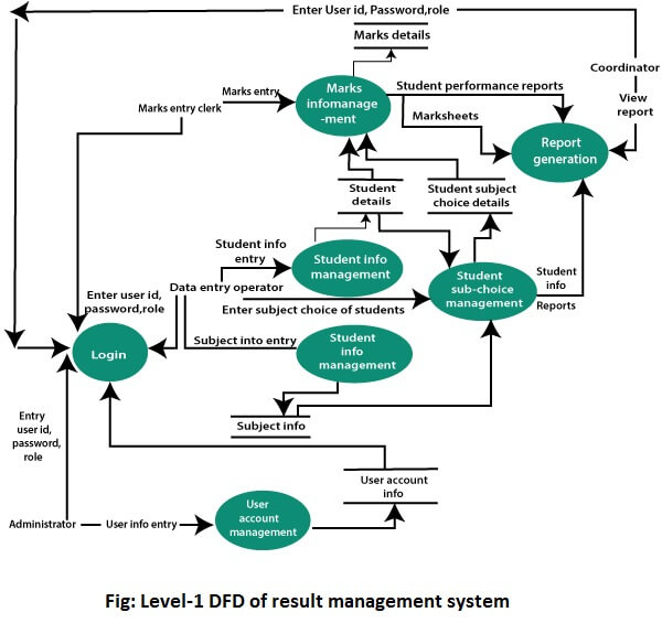
This optimization reduces unnecessary data transfers, transformations, and computations, resulting in faster and more streamlined data processing. For each data flow, at least one of the endpoints (source and / or destination) must exist in a process. The refined representation of a process can be done in another data-flow diagram, which subdivides this process into sub-processes. While level 1 DFDs are still broad overviews of a system or process, they’re also more detailed — they break down the system’s single process node into subprocesses. Data flow components are the pipelines through which the data is transferred in the system.
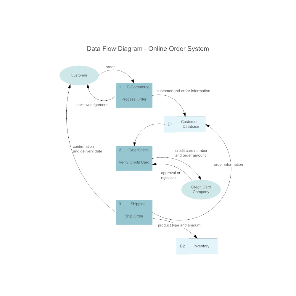
Lucid is proud to serve top businesses around the world, including customers such as Google, GE, and NBC Universal, and 99% of the Fortune 500. Lucid partners with industry leaders, including Google, Atlassian, and Microsoft. Since its founding, Lucid has received numerous awards for its products, business, and workplace culture. Nearly every process or system begins with input from an external entity and ends with the output of data to another entity or database. Identifying such inputs and outputs gives a macro view of your system—it shows the broadest tasks the system should achieve.
They can also be displayed on the Agent Desktop, with customization options available in Flow Designer. You can also start with the output data stream that denotes the software’s output. Further, you have to trace the output stream backwards to create the design. The bubble is labelled with the verb that transforms the input data to output data.
Analysts can initiate the exploration at a higher level, capturing the essence of the entire system, before progressively zooming into the nuances of individual processes. This methodical progression ensures that the system is comprehensively documented while allowing for detailed elaboration where necessary. A data flow diagram can dive into progressively more detail by using levels and layers, zeroing in on a particular piece. DFD levels are numbered 0, 1 or 2, and occasionally go to even Level 3 or beyond. The necessary level of detail depends on the scope of what you are trying to accomplish.
Double-click on an entity, process, or data store, and then click and hold one of the orange circles and drag the line to the appropriate symbol. Data flow diagrams became popular in the 1970s in software development. They were first described in a classic text about Structured Design written by Larry Constantine and Ed Yourdon.


No comments:
Post a Comment